
The Hercules Motor Controller Board
First, if you don't have the Arduino Integrated Development Environment (IDE) installed, please download and install it from this following link: https://www.arduino.cc/en/Main/Software
Once you go to the link above, scroll down to the following section:

If you are using a Windows PC, click on Windows Installer link for fast and easy installation process.
If you are using a Raspberry Pi, click on the Linux ARM link. For other Linux distros (Ubuntu, etc...) use either Linux 64 or Linux 32 depending on what operating system you have installed.
Once you open the link above, click on 'clone or download' then 'Download ZIP' (YOU DON'T HAVE TO EXTRACT IT).

Now, open the Arduino IDE. You should see a window that looks similar to this:

Click on Sketch > Include Library > Add .ZIP Library

After you click on 'Add .ZIP Library', a window will pop up. Locate the library ZIP file you downloaded from github, click on it then click on open.

Now, it is time to connect the board. Use female-to-female jumper wires to connect the UartSBee to the Hercules motor controller.

Female-to-Female Jumper Wires


Make sure you connect the wires correctly:
DTR on to the Hercules Motor Controller < > DTR on the UartSBee
TX on the Hercules Motor Controller < > RXD on the UartSBee
RX on the Hercules Motor Controller < > TXD on the UartSBee
5V on the Hercules Motor Controller < > VCC on the UartSBee
GND on the Hercules Motor Controller < > CTS on the UartSBee
GND on the Hercules Motor Controller < > GND on the UartSBee
Now, we will use a micro USB Type B cable to connect the UartSBee to a PC or a Pi.
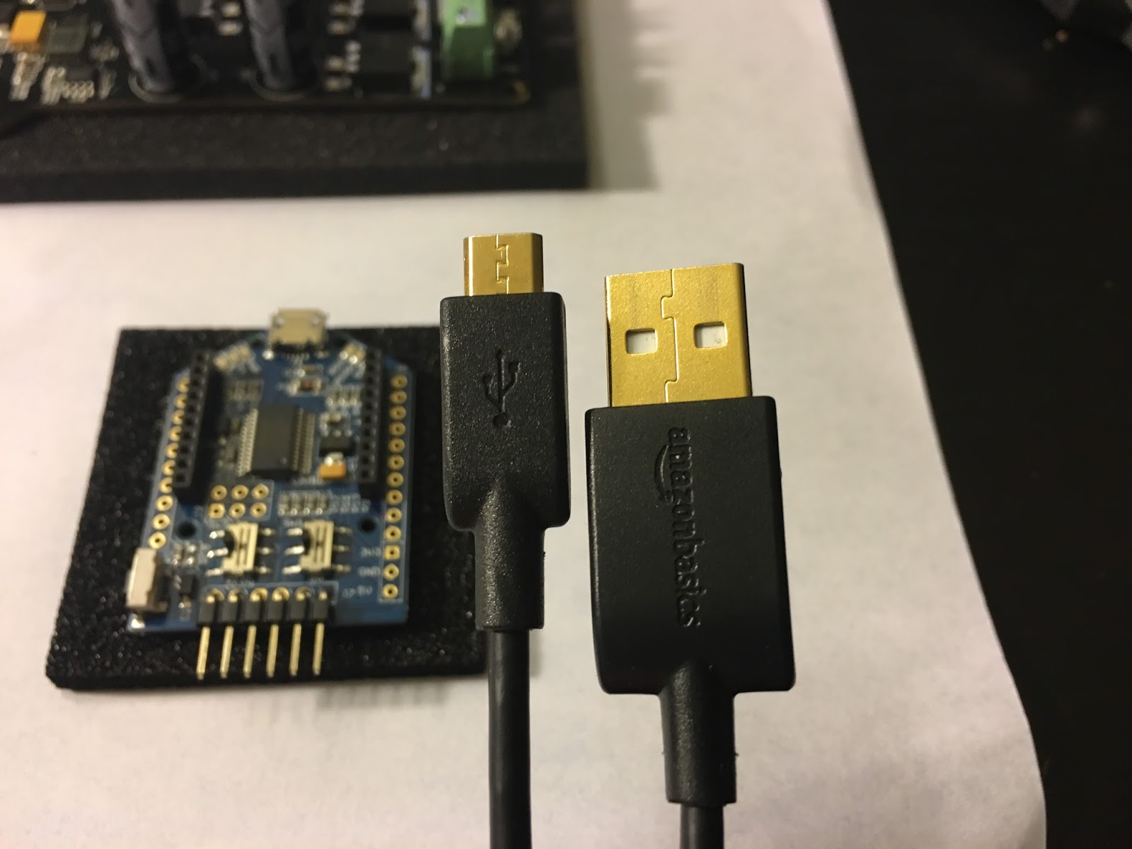
Micro USB Type B Cable


Once you have connected the USB cable to a PC, wait few seconds for the UartSBee device to be automatically recognized and installed by the operating system.
Moving on, close the Arduino IDE then reopen it. From there, click on Tools > Boards, select Arduino Duemilanove or Diecimila.
Why do we do this? the microcontroller on the Hercules board is an ATmega328P, the same microcontroller on the Arduino Duemilanove. So, in order to program the Hercules, we need the IDE to know which type of microcontroller it is dealing with to avoid any compatibility issues.

To make sure we have the correct processor, go to Tools > Processor > ATmega328P

Then make sure to select the USB port (if you have one microcontroller connected, then only 1 port will show up on the list).

Now we are ready to program the controller. Let's use an example provided by the library. Click on File > Examples, scroll down all the way until you see 'Hercules_Motor_Driver-master', click on it and select 'DC_Motor'

After doing so, a new window will open that contains source code for the example you selected:

Now click on the check mark on the top left, and wait for a green bar to load on the bottom right. After the green bar finished loading, you will see a message saying 'Done Compiling'. Now click on the right arrow icon (next to the check mark) or press Ctrl + U, then wait for the green bar to load and for a confirmation message saying 'Upload Complete' or 'Upload Successful' to show up.